BB-8
Hello, I'm Eric Boehlke. I have been building robots for 9 years now. This is my favorite one yet. All of my previous robotics projects have been made with the LEGO NXT robotics system. NXT is a kit LEGO puts together that provides an easy way for people to get into robotics. They provide the brain of the robot, development environment, motors, sensors and, of course, building blocks. As I have gotten more involved in robotics, I have thought of bigger, more complicated robots, both to build and to program. This year’s project was just too much for LEGO. I dove into the world of non-LEGO robotics and tried to learn as much as I could, while attempting to create a life-sized BB-8 robot from the Star Wars Episode VII movie trailer, which was released in November. When I first saw the trailer, I was amazed at the new droid being introduced into the Star Wars universe. I wanted to build my own.
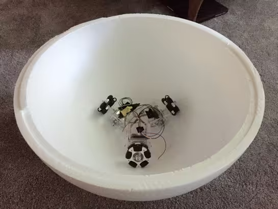
This project started in early June. I was just beginning to look into what type of development platform I could use for the robot. My dad’s coworker lent me his BeagleBone Black to check out and to see if it was something I wanted to use. The BeagleBone Black is a low-cost micro-computer with many connectivity options making it great for robotics. I designed my version of BB-8 with two robots that work together to achieve the right motion. One robot would balance on top of the ball and another, inside the ball, would steer. Everything in this project was new to me. I needed to learn about a new development platform, learn how to program with different motors, figure out how to wire up sensors, learn a new language, and many more things. I felt well prepared for this challenge because of all of my previous years of robotics. I had so much fun! This project taught me so many new things about robotics, such as building and designing the frame, Kalman filters, pros and cons of different programming languages, how to choose batteries, PID controllers, and much more. Although my BB-8 is not perfect, I have learned a great deal and I plan to continue to improve the robot and learn more about robotics.
There are some additional pictures in this album.
Construction
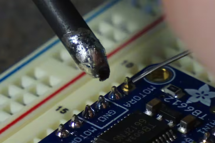
Wiring the Electronics
My parts arrived and the first step was to solder the headers onto the motor driver breakout board. Then, I was ready to wire up the board to my new BeagleBone Black and the stepper motor. I started programming in JavaScript. I followed the tutorials on Adafruit.com. I had a little trouble getting the motor to spin. All it did was twitch. I used my multimeter to check the connections and discovered that there was only 1 volt of energy going to the motor. I did some research and found out that the 5 volt power pin only gives 5 volts when a barrel jack is connected. I used the system power pin and I got my motor spinning. The next step was to get all three motors to spin. I soldered the headers to the rest of the boards and realized that I needed a bigger breadboard. I wired up the motors to the BeagleBone Black and started programming.
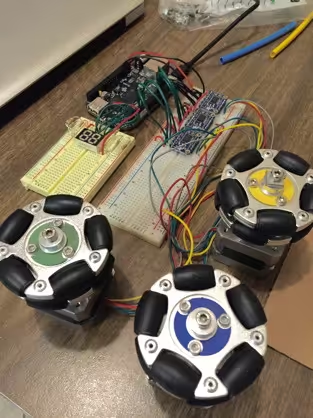
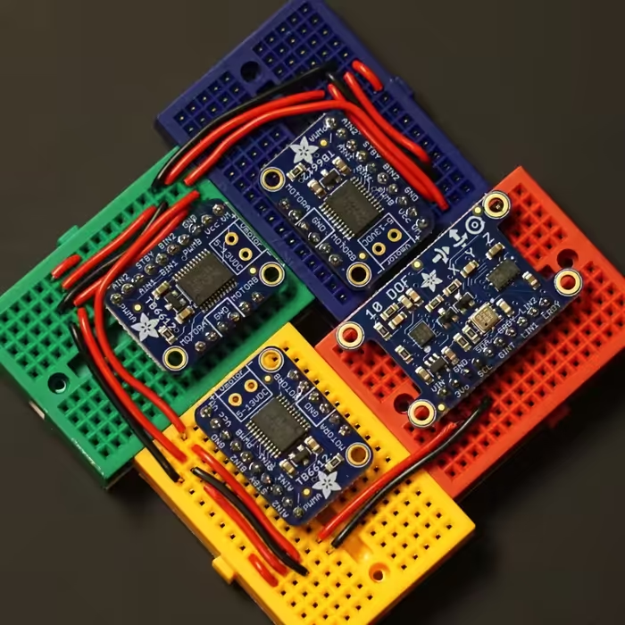
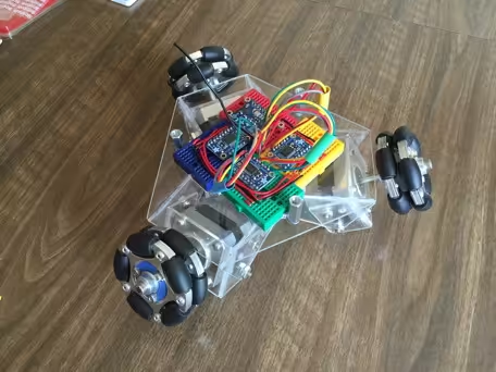
I found that JavaScript was too slow to run even one motor at full speed, 50 rpm. I needed a new language that was compiled rather than interpreted. I chose Python. It was fast enough to run all three motors at full speed and much more.My program was able to run the stepper motors at full step and half step. I was happy to get the motors to half step because that meant that I would have better precision movements of my robot. The bigger breadboard was too big to fit in the robot so I chose to use 4 smaller breadboards that I attached together in a square. This allowed the wires from the bottom of the breadboard to be fed up through the hole in the middle of the breadboards and the wiring was very compact.
Designing the Frame
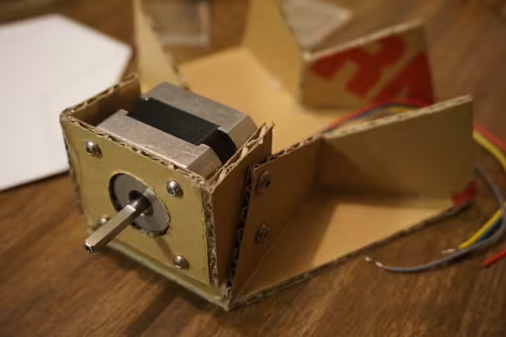
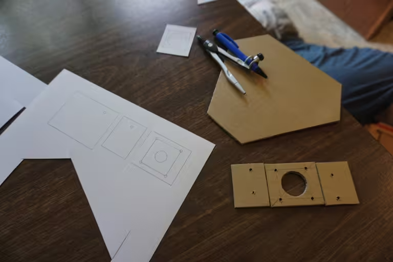
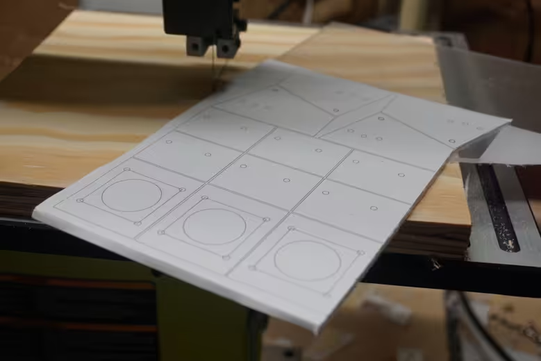
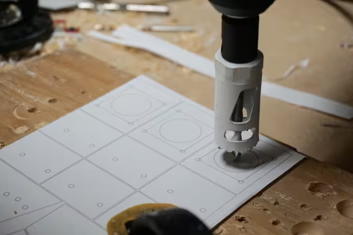
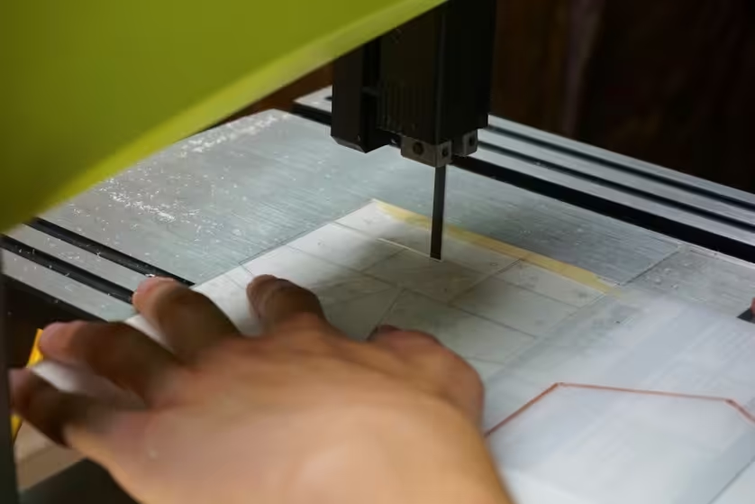
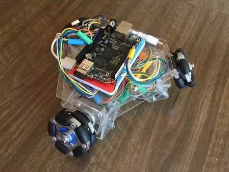
To make the frame I first designed it on the computer using SketchUp and Omnigraffle. Then, to test out the design, I cut the pieces out of cardboard and hot glued them together. I bought some screws to attach the cardboard pieces together. Since one robot was going to be inside the ball and one on top, the wheel and motor assembly had to be positioned perpendicular to the surfaces of the ball. I did not know the correct angle ahead of time and could not measure it until I had made a frame and installed the wheels. I decided to allow the wheels to tilt into whatever position they needed to make good contact with the ball. Allowing the motors to tilt also allows the robot to drive on level surfaces for testing. After I had settled on a design that I liked, I chose the material I would use to make the final robot. I wanted to see all of the wire and motors so I used .093” sheets of acrylic to build the frame. I stuck the template onto the acrylic with a glue stick. Then, I cut the pieces out on the bandsaw and drilled the holes.
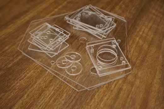
Assembling the Frame
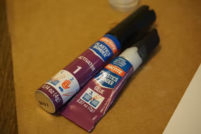
When all of the parts were cut out, I had to glue them together. I used Loctite 2 part plastic glue. This glue melts the plastic and fuses the 2 pieces together. Once the pieces were glued, I attached the separate pieces of the frame together with the screws.
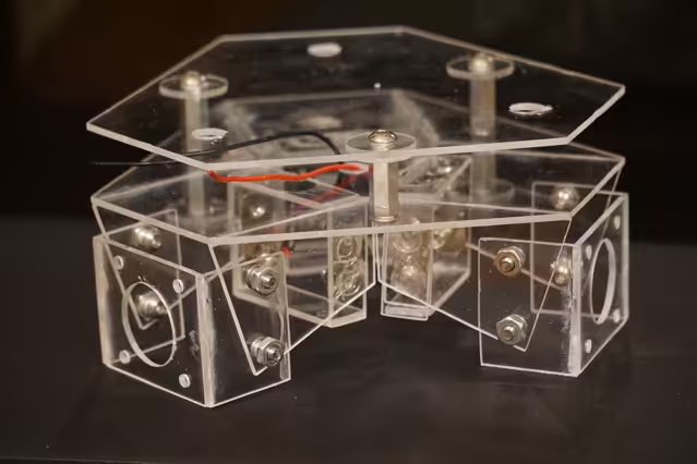
Once the frame was assembled I attached the motors. I attached the wheels and then it was time to measure the angle the wheels had to be at to make good contact with the inside and outside of the ball. I marked the positions of the screws and drilled the holes.
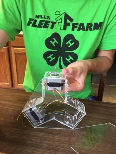
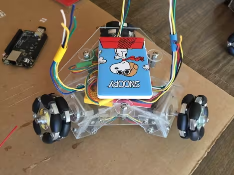
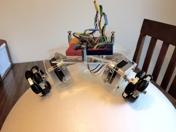
The next step in assembly was to attach the electronics. I put colored hubcaps on the wheels and used those colors throughout my robot. The blue motor wire had blue shrink tubing, was attached to the blue breadboard, and had wires going up to the BeagleBone Black that were kept together with more blue tubing. I did the same process for all of the motors and carefully wired up the robot. The colors allowed me to quickly find and fix any electrical problems and they helped with programming. I attached the BeagleBone Black onto the top of the robot with foam tape.
Batteries
I was almost done with the frame of the robot. All that I needed were batteries to power the motors and the BeagleBone Black separately. The BeagleBone Black only needs 5 volts and 1 amp, so I chose to use a cellphone charger with the same dimensions of the BeagleBone Black. The batteries for the motors were harder to find. I first went to Batteries Plus to see if they had any 6 - 12 volt batteries that could supply 1 amp, had around 2 amp-hours of capacity, and that could fit in the tiny space in the bottom of my robot. It was then that I realized that I should have designed the robot with the batteries in mind. I ended up trying CR123 batteries that are used in cameras. They are 3 volts and with 3 batteries in series and 2 groups of the 3 in series wired in parallel, I figured that they would give me the right amount of power and run time. I tested out many configurations of the batteries to try to fit them in the robot. I ended up putting a battery pack containing 2 batteries in parallel in each of the 3 sides of the robot. I then wired the 3 battery packs in series to give 9.7 volts and 1 amp.
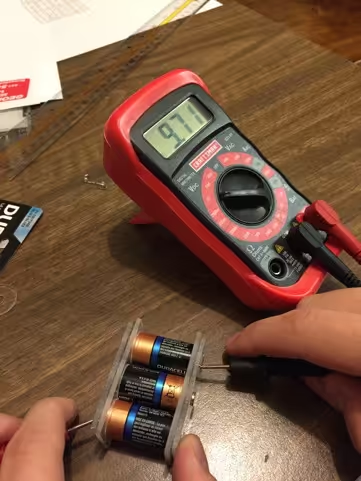
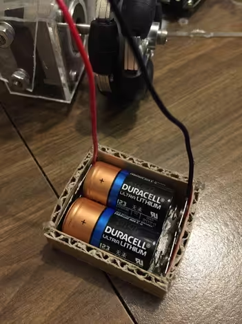
The batteries did not have the run time I wanted so I needed a new plan. I bought 2 USB battery packs used for charging cell phones. They delivered 5 volts at 1 amp and claimed to have 2600 milliamp-hours. I thought that these batteries would be great. They should power the robot for around 2 hours and they were pretty inexpensive. I found out that they do not have 2600 milliamp-hours as they only lasted about half an hour in the robot. I bought 4 of them, 2 for each robot and when I got them 2 could not hold a charge and were totally dead. It turns out they were not very high quality batteries. I bought 2 more expensive batteries and am hoping they last longer. I also decided to power the robot from a wall adapter that delivered 9 volts and could supply 2.5 amps, plenty for the motors.
Building BB-8's Body
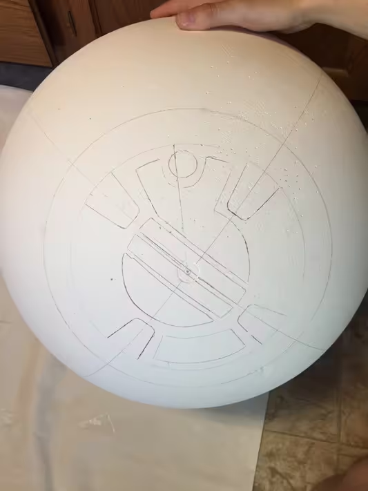
Now that I had the robot part done, I needed the ball for the robots to go into and to balance on. My first idea was to cover a playground ball with paper maché 1 inch thick on all sides. I planned to cut the ball in half and think of some way to make the two halves lock together, and then come apart when twisted, in order to remove the robot. After the first layer of paper maché, I realized that this plan would take far too long. I remembered a video I had watched about a different person making a BB-8 robot. He mentioned that he used a hollow styrofoam ball that came in 2 parts that locked together. This was a very good idea and much faster than the paper maché plan so, I decided to order some styrofoam balls online. I turns out that very few of these balls are made in the U.S., so I had to order a 50 cm diameter ball from the U.K. The head is also a sphere so, I ordered a smaller 30 cm diameter ball as well. I wanted to paint the designs on the ball to make my robot look like the droid in the Star Wars Episode VII trailer. I decided that gesso, a paste that is typically brushed onto canvases to prepare them for paint, would help the paint stick to the styrofoam and provide a little protection to the ball. I applied two coats of gesso and let them properly dry. I made the designs on the ball and the head using templates I found online and the video of BB-8 on stage at the Anaheim Star Wars Celebration. I traced the outlines of the shapes onto the ball and then painted the surface. I used acrylic paint and mixed the colors to match BB-8 as closely as possible. I dipped a Lego piece in paint and used it for the circles around the ball. I made the eye piece from a plastic Christmas ornament painted black.
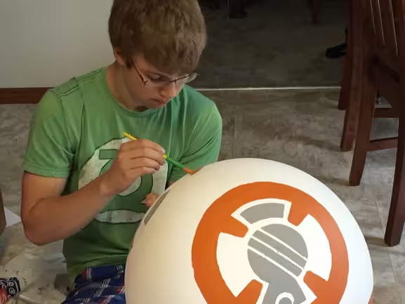
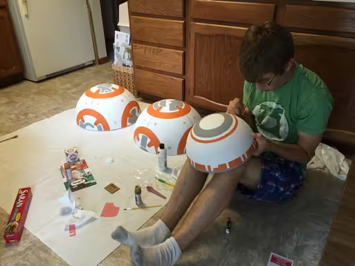
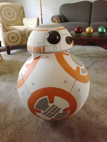
The Final Result
The robot balances on the ball pretty well as long as it is on carpet and the second robot is in the ball. I still have much work to do to improve the balance and make it move around.
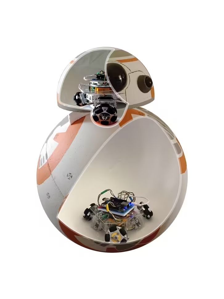
Parts
DEVELOPMENT PLATFORM
- (2) Adafruit - Element 14 BeagleBone Black Rev C - 4GB - Pre-installed Debian
- (2) Amazon - D-Link Wireless N-150 Mbps USB Wi-Fi Network Adapter (DWA-121)
BREAKOUT BOARDS
- (2) Adafruit - 10-DOF IMU Breakout - L3GD20H + LSM303 + BMP180
- (6) Adafruit - TB6612 1.2A DC/Stepper Motor Driver Breakout Board
- (2) Teenitor (via Amazon) - 170 Points Mini Breadboard for Arduino Proto Shield (6 PCS)
MOTORS AND WHEELS
- (6) Adafruit - Stepper motor - NEMA-17 size - 200 steps/rev, 12V 350mA
- (6) RobotShop - 5mm Aluminum Mounting Hub (RB-Nex-98)
- (6) RobotShop - 60mm Aluminum Omni Wheel (RB-Nex-75)
FRAME
- Frame Template PDF
- (2) Home Depot - OPTIX .093 in. x 11 in. x 14 in. Clear Acrylic Sheet
- Hardware Hank - Miscellaneous Hardware
BODY
- Artwork Template PDF
- (1) Craftmill - 50cm 20inch Polystyrene Balls in 2 hollow halves
- (1) Craftmill - 30cm x 1 Polystyrene Ball in 2 Hollow Halves
- Hobby Lobby - Miscellaneous Paint
BATTERIES
Programming
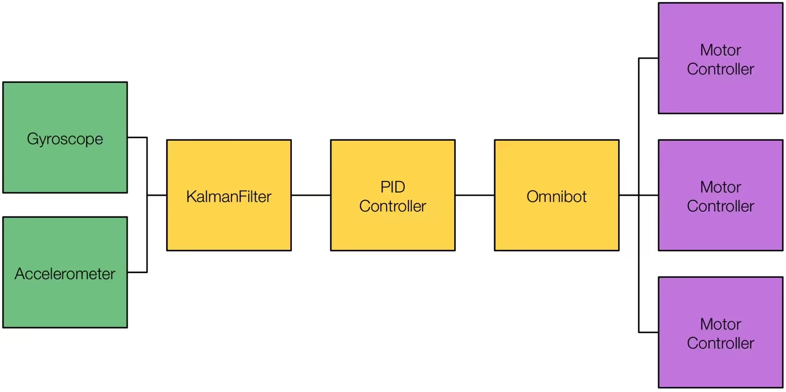
For a robot to balance well it needs at least 2 sensors to help it know when it is falling. Those sensors are an accelerometer and a gyroscope. The accelerometer measures the forces acting on the robot including the movement of the robot. The accelerometer is very noisy, meaning it does not give very precise data, and is affected by the movement of the robot; however, the accelerometer always knows which way is up. The gyroscope measures the angular velocity of the robot. It is very precise but, it only measures the angular velocity and not pitch and roll. At first I thought that I would only need one of these sensors to have the robot balance; however, neither one is very good alone. The gyroscope cannot be used to make a reliable balancing robot because it does not know when it is level. The angular velocity could be measured over a short period of time and be converted into a distance traveled and all of the distances be added up over time but, the gyroscope would start to drift and the longer the program would run the more the tiny errors in the calculation would add up and eventually the robot would fall off. The accelerometer would work for a longer period of time but it would be very imprecise and the robot would quickly fall off the ball. To make a good balancing robot the values from the accelerometer and gyroscope have to be combined.
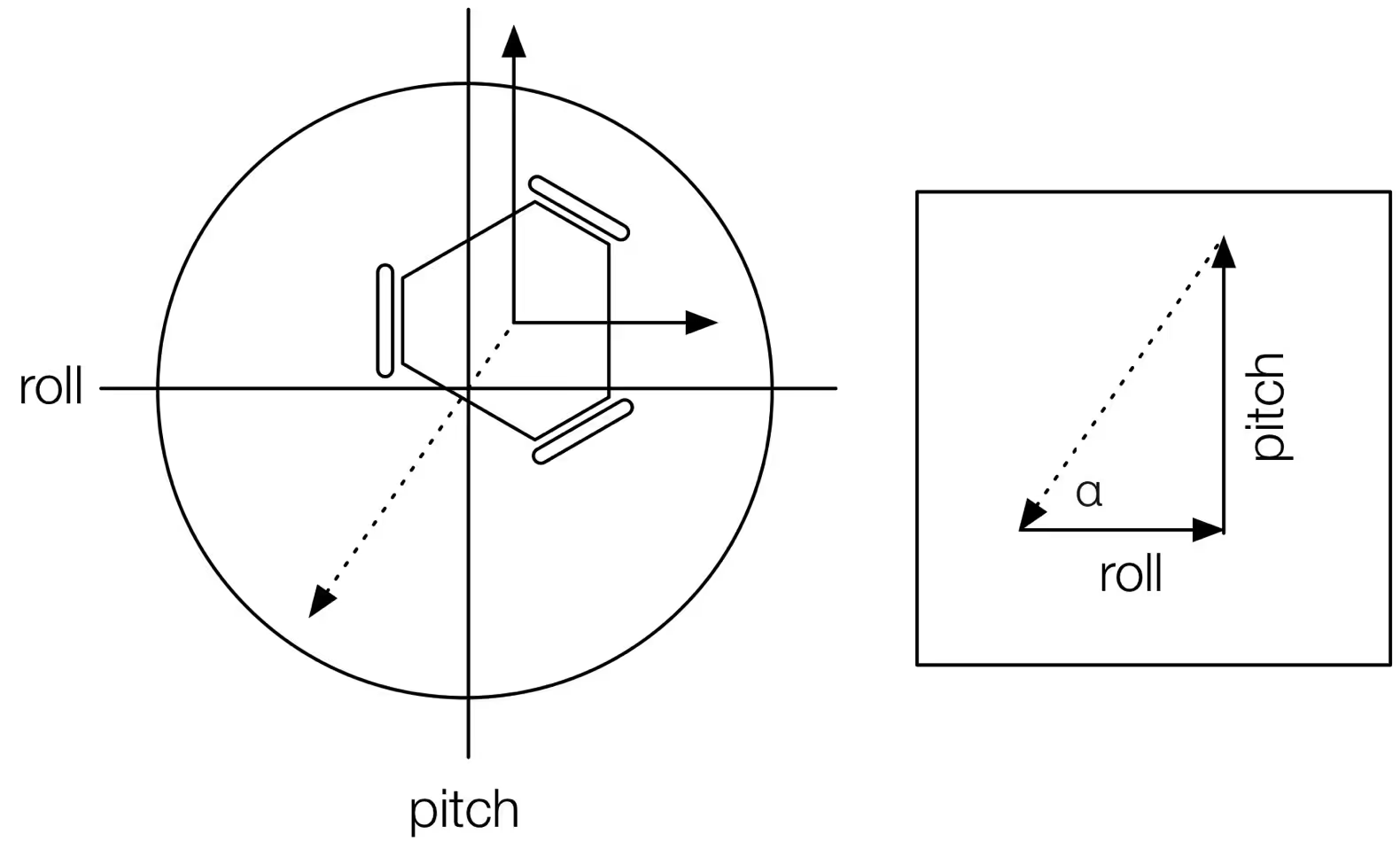
The best way to combine the data is by using a Kalman filter. I have tried other kinds of filters and have seen that this one gives the most accurate results. The Kalman filter takes the gyroscope and accelerometer values and calculates the amount of trust each one deserves. It can change the amount of trust while running and gives a much more accurate reading that the complementary filter. Once the pitch and roll are calculated by the Kalman filter the robot takes the arctangent of the two values to find the driving angle.
The robot also needs to know how fast to go. If it is near the center of the ball it should move slower than when it is about to fall off. The best way to calculate the speed is to use a PID controller. PID stands for Proportional Integral Derivative. It basically lets the robot act in proportion to the distance from the center while keeping it from going too far and allowing the robot to react quickly to any sudden changes.
The driving angle and the driving speed are given to the robot which can calculate how fast each wheel should turn to achieve the desired direction and speed. The motor controller program turns the speed of the wheels into electrical signals that are given to the motor controller breakout boards to turn the motor.
References
- Adafruit “L3DG20H Gyroscope Datasheet”
- Adafruit “LSM303DLHC Accelerometer Datasheet”
- Adafruit “TB6612FNG Stepper Motor Driver Datasheet”
- Adafruit “Stepper Motor Datasheet”
- Element 14 “BeagleBone Black Rev C Reference Manual”
- Lauszus, Kristian “A Practical Approach to Kalman Filter and How to Implement It”
- Python Software Foundation “Python Language Reference”
- “What is a Stepper Motor?”
- XRobots “Star Wars EP7 BB-8 Droid Build”
- X-firm Systems “Balancing Robot for Dummies”
Updates
BB-8 Around the Web
A running list of the places my BB-8 has shown up online, so I can keep track of them in one spot.